As we discussed earlier, we have some very old wiring that we are starting to address this week. So if you go to the church for any reason, please be aware that some electrical circuits are turned off. -DO NOT turn any breakers back on- since we have open wiring that is being addressed. I have attached some pictures of the ongoing work and there is a short summary of what we have found below. We hope to have the main church lighting and front outlets working again by Sunday.
First, some history as noted on our web page:
1899 Inside covered with “corrugated tin” (what we would now consider to be “pressed tin” as often seen on antique ceilings of other century old local buildings – this was a popular interior choice between 1880 and 1930 in the US)
1900 Electric lights were installed
1903 Basement built.
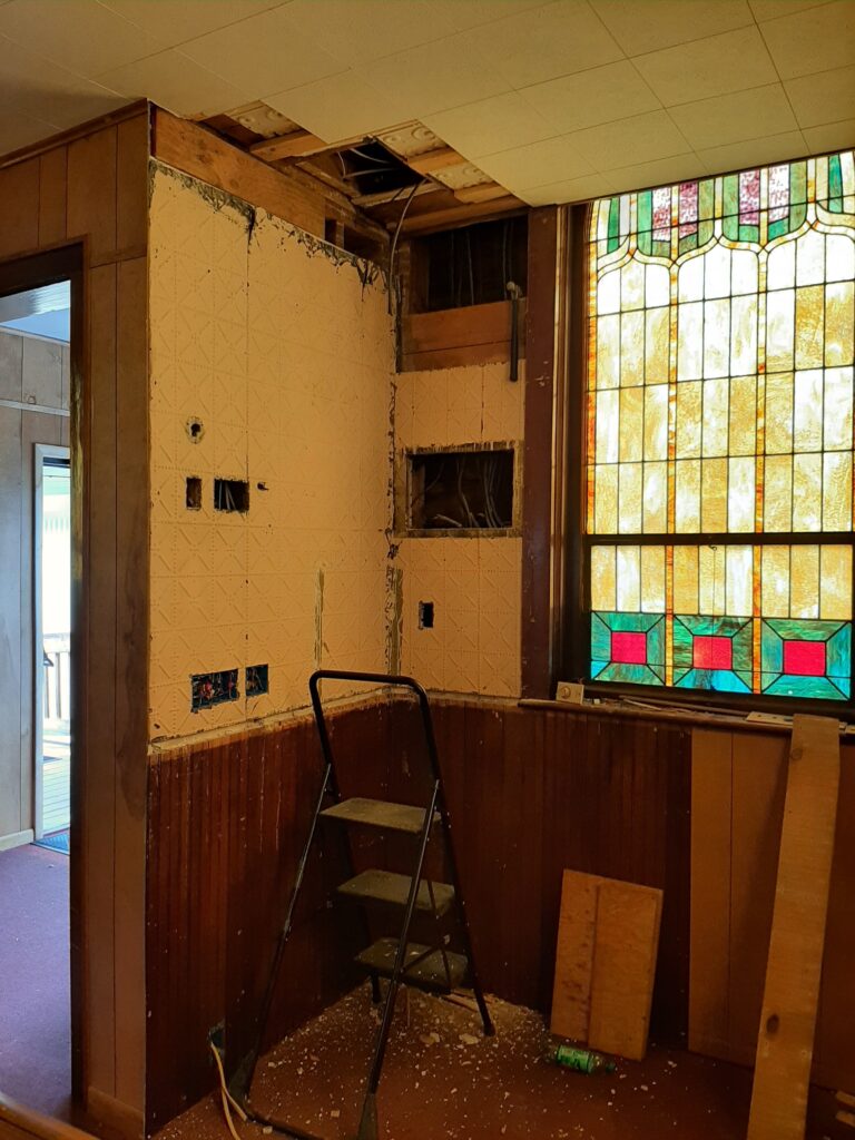
Picture 1. The opening in the center of the wall is where the original 1900 electric service was installed. Yes, that is the original wiring that was installed in 1900 that you can still see where the new “corrugated tin” installed in 1899 (the year before) was cut out. There is a splice there that attaches “newer” 50’s electric wiring to that original Knob and Tube wiring. That goes to a junction box in the basement which then attaches to modern romex wiring (with ground wires that don’t exist in the other two) There would have been 4 fuses for 4 circuits in the original box. All of these circuits and wires were still in use, but they have been spliced into and/or cut off in numerous locations as things were added and changed over 124 years. Many of these additions were done by pulling up floorboards in the balcony or placing wiring between the paneling and tin wall. Since the organ pipes cover these areas now, new wiring is going to require new pathways and therefore we had to remove the sections of wall towards the ceiling for access. You can see some of the original old Knob and Tube wiring that fed the wall switches hanging from the ceiling opening as well.
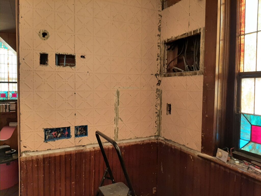
Picture 2. Here you can see that there used to be a light fixture (or two) on the wall above the original switches (the higher cut open portions on the left) in our coat rack alcove. We have removed those switch boxes and new ones were added at an Americans with Disabilities Act height. We figured once the wall was open, now is the time to fix some things to bring us closer to the current electrical standards if it was within reason. You can get a better idea of the wall pattern tin (in pink paint) from this picture. Also you can see the original clear pine wainscoting and the Knob and Tube splices noted in picture one. Also, it should be noted there was no insulation in this wall space in general… only a little piece of balsam wool in the original electric box location….. perhaps because Reino knew at some point we would want to rewire it? Adjoining spaces were insulated. We will insulate once we have the new wiring in place.
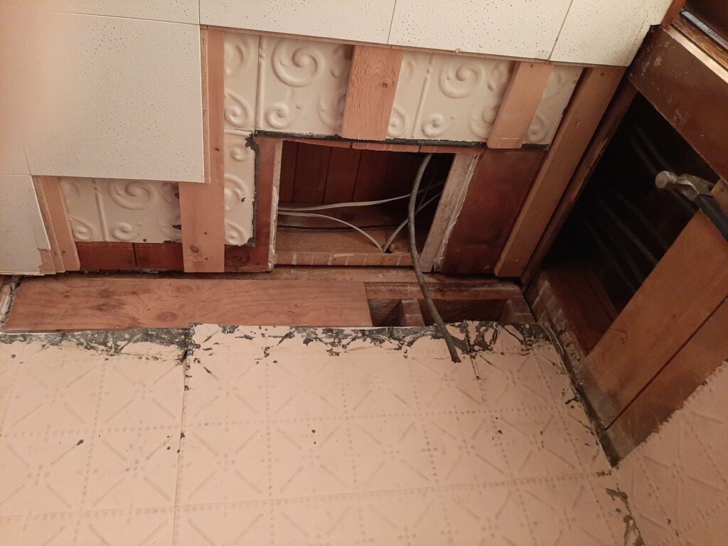
Picture 3. This one show the tin pattern below the balcony on ceiling and the pattern (different) on the walls. This is the space we had to work in to get new wiring installed to the entry light, and under balcony lights. Some wiring for outlets in the balcony was buried in this space as well but we had no reasonable access so we had to find a different path to power those spaces.
Some things we’ve run into:
1. There were no junction boxes installed for the entry and under balcony lights. The light were attached directly to the paper ceiling tiles. The fixtures had run so hot with regular bulbs that coatings on the wires were scorched and in one case bare wire was touching the fixture base. These will all have to be replaced, new boxes cut in and re-fed with new wire.
2. Multiple locations had wire nuts installed, but the wires were -NOT- twisted in the nut. So any pull on the wire would cause the connection to just come apart. (another arcing hazard)
3. I had thought that the front of the church was fed through the basement. A closer look at the history above though shows the reason that isn’t true. The wiring was installed 3 years before we had a basement! So it all feeds through the attic. Of the 4 original circuits, we are working on replacing 3 of them. The final 4th circuit comes from the basement through all the junctions mentioned in the picture one notes, from there it goes up the wall to the attic, then down the church rafters to above the pulpit, then across the church attic to the parking lot side and then runs down the front wall by the stairway….. where it then feeds : all of the alter lights (upper and and lower), the outlets on either side, all of the pastors office lights and outlets, the front stairway lights, all of the downstairs Rec room lights, the Kitchen lights, some downstairs outlets, all of the back shed lights and outlets. This is a -very- long run of wire with -many- items on it. This isn’t great, but we would have to do a -LOT- of destruction to get access to -ANY- of these areas, so for now, even though this is also the circuit that was hit by our lightning strike, we are leaving this circuit in place. If, at some point, we get access to the basement ceiling we would rewire these devices from the bottom.
4. As noted above, as we move some switches around, we will have some holes in the paneling that will need to have blank covers put on them for now. Or if you have picture you like, perhaps we can hang that over them ; )
As always, we thank you for your building fund contributions that let us do this work, and we welcome your comments or suggestions
Thanks!
David